With bearings being used across such a wide range of industries and applications, you would expect their design to be fully standardized and to have to comply to very strict
international regulations. However, only a part of a bearing’s designation is currently regulated by standards issued by international bodies like ISO or ANSI.
This leaves manufacturers plenty of space for innovation and for coming up with designs that are specifically engineered to help distinguish themselves from other producers,
while facilitating international bearing interchangeability and economical bearing production.
For consumers though, the lack of stricter standards means a multitude of unique part numbers that are specific to each manufacturer. These series are engraved or stamped on
the products and can be easily retrieved when replacing a bearing. Still, if you plan to switch to a different brand or product, you need to
know what the bearing designations mean in order to find suitable alternatives.
So how do you navigate the seemingly chaotic bearing designation systems?
What do numbers in bearing series codes mean?
In our Guide to bearings, we’ve detailed the various types of bearings used in industrial applications and
their structural and functional differences. In this article we’ll focus only on rolling-element bearings (ball bearings and roller bearings). If you’re not yet familiar with
this type of bearing, go ahead and read our beginner’s guide first.
Now let’s see how to read the roller bearing designations for some of the most popular brands on the market!
Typically, a roller bearing’s designation includes a basic number (designation), surrounded
by supplementary codes - suffixes and prefixes. The suffixes and prefixes describe the tolerance, internal clearance and other
design particularities.
The basic designation contains 3 to 5 digits and gives general information about the bearing,
describing its:
- type
- boundary dimensions – width (B, C, T or H), outer diameter (D), bore diameter (d), chamfer dimension (r)
- series number
- contact angle
So a typical basic bearing designation looks like this: A BC DE, where:
- A – Bearing type
- B – Width
- C – Outer diameter
- DE – Bore diameter
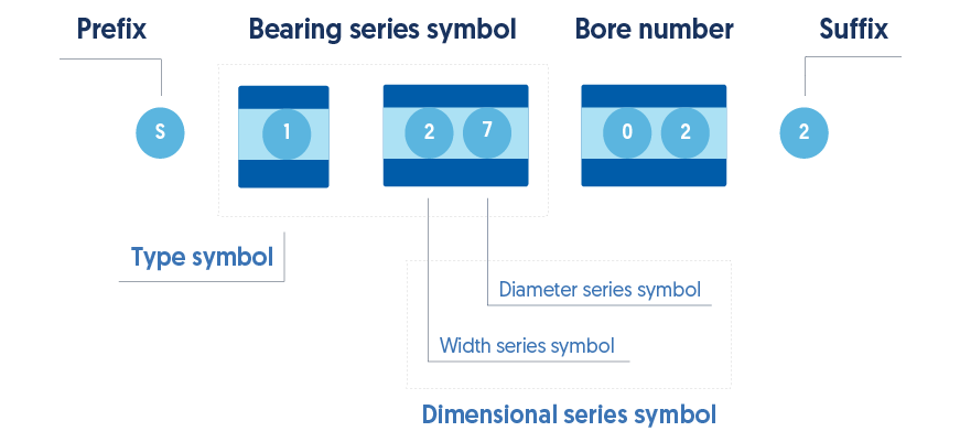
The boundary dimensions that are internationally standardized include the width and the outer diameter (B, C).
Together, these are also referred to as the dimensional series of the bearing. The dimensional
series (BC) along with the bearing type (A), so the first three digits of the number, form the bearing
series symbol (A BC).
The bore diameter is given as a 2-digit code (DE), which needs to be multiplied by 5 to give the actual bore diameter in mm. However, this rule only applies to bore diameter
dimensions greater than 20 mm. Under this value, the bore diameter uses the following code identifications:
| Bore diameter |
10 mm |
12 mm |
15 mm |
17 mm |
| Code |
00 |
01 |
02 |
03 |
When suffixes and prefixes are added, the bearing designation will look like this: Prefix A BC DE
Suffix
The suffix can be separated from the rest of the designation number by a space, a hyphen or an oblique stroke. The codes for bearing
types are as follows:
| Bearing type |
SKF |
NSK |
Timken
| FAG |
| Double row angular contact ball bearing |
0 |
3, 5 |
|
3 |
| Self-aligning ball bearing |
1 |
1 |
1, 2 |
1 |
| Spherical roller bearing, spherical roller thrust bearing |
2 |
2 |
2 |
2 |
| Tapered roller bearing |
3 |
3 |
3 |
3 |
| Double row deep groove ball bearing |
4 |
4 |
|
4 |
| Thrust ball bearing |
5 |
5 |
5 |
5 |
| Single row deep groove ball bearing |
6 |
6 |
6 |
6 |
| Single row angular contact ball bearing |
7 |
7 |
7 |
7 |
| Cylindrical roller thrust bearing |
8 |
|
8 |
|
| CARB toroidal roller bearing |
C |
|
|
|
| Cylindrical roller bearing. Two or more letters are used to identify the number of the rows or the configuration of the flanges |
N |
NU, N, NU, NN |
NU, NN, N, NF |
N, HCN, NN, NNU |
| Four-point contact ball bearing |
QJ |
|
|
QJ |
| Tapered roller bearing in accordance with ISO 355 |
00 |
01 |
02 |
03 |
| Separable ball bearing |
|
BO, E, L |
|
|
As you can see, these codes are fairly agreed upon throughout the industry.
- The letters BC in the code above indicate how wide the bearing is, and what the external diameter is.
- For the outer diameter, the series numbers go from 7 – 8 – 9 – 0 – 1 – 2 – 3 – 4, with 7
being the smallest and 4 being the largest diameter.
- For the width of radial bearings, the codes go from 8 – 0 – 1 – 2 – 3 – 4 – 5 – 6,
with 8 being the smallest and 6 the biggest.
- For the height of thrust bearings, the codes go from 7 – 9 – 1 – 2, with 7 being
the smallest and 2 the biggest.
When it comes to suffixes and prefixes, things vary much more. Prefixes are used for defining the components of a bearing or variations.
Suffixes are used to indicate design particularities such as the bearing internal design or external design (seals, snap ring groove),
cage design, materials and heat treatment, the tolerance, clearance, preload and so on.
Below you can find common suffixes and prefixes used in roller bearing designations.
Prefixes - NSK Bearings
| Meaning |
Bearing with special dimensions |
Bearing with flanged outer ring |
Higher load rating |
Miniature metric bearing with special dimensions |
Bearing outer ring with rollers and cage, no inner ring |
Miniature bearing made from extra corrosion-resistant steel |
| Code |
B |
F |
HR |
MR |
R |
-H- |
Suffixes - Clearance
| Meaning |
Normal radial internal clearance (RIC) |
Radial internal clearance smaller than C2 |
Radial internal clearance smaller than normalRadial internal clearance greater than normal |
Radial internal clearance greater than normal |
Radial internal clearance greater than C3 |
Radial internal clearance greater than C4 |
| Code |
C0 / CN |
C1 |
C2 |
C3 |
C4 |
C5 |
To learn more about the bearing clearance and its values, read our article Bearing clearance: everything you need to know.
Other suffixes from various brands
| Meaning |
SKF |
NSK |
Timken |
FAG |
| Angular-contact ball bearing with 30° contact angle |
A |
A |
T |
|
| Angular-contact ball bearing with contact angle of 25° |
ACD |
A5 |
A |
E |
| Angular-contact ball bearing with contact angle of 40° |
B |
B |
J |
B |
| Double-row angular contact ball bearing with contact angle of 25° |
B |
B |
|
B |
| Universal angular-contact ball bearing with contact angle of 40° |
BG, B(E)C |
BG, BWG |
|
BUA |
| Angular-contact ball bearing with contact angle of 15° |
CD |
C |
|
C |
| Spherical roller bearing with high load capacity, machined cage |
|
CA |
|
|
| Spherical roller bearing with high load capacity, pressed cage |
|
CD |
|
|
| Deep groove ball bearing with d <10mm and contact seal on one side |
RS1 |
D |
|
RSR |
| Deep groove ball bearing with d <10mm and contact seal on both sides |
2RS1 |
DD |
|
2RSR |
| Deep groove ball bearing with contact seal on one side |
RS1 |
DU |
|
RSR |
| Extra capacity design |
E |
E |
|
E |
| Tapered bore (taper 1:12) |
K |
K |
|
K |
| Solid brass cage, rib-guided |
MA (MB) |
M |
|
MA (MB) |
| Solid brass window-type cage |
MP |
MA1 |
|
MP |
| Solid brass cage, outer ring rib-guided |
MA6 |
MB |
|
M1A |
| Solid brass cage, guided by rolling elements |
M |
MR |
|
M |
| Bearing with snap ring groove in the outer ring of the bearing |
N |
N |
|
N |
| Polymer cage |
T |
T |
|
T |
| Pressed steel cage, one-piece |
J |
W |
|
J |
| Full complement roller bearing |
V |
V |
|
V |
| Non-contact seals on both sides |
2RZ |
VV |
PP |
2RSD |
| Deep groove ball bearing with single shield |
Z |
Z |
D |
Z |
| Deep groove ball bearing with double shield |
ZZ |
ZZ |
DD |
ZZ |
| External dimensions in line with ISO |
X |
X |
|
X |

Do you have questions about our products?
For personal advise and product knowledge, visit an ERIKS location near you or contact our product specialists.
Find a service center | Call us | Send us an e-mail